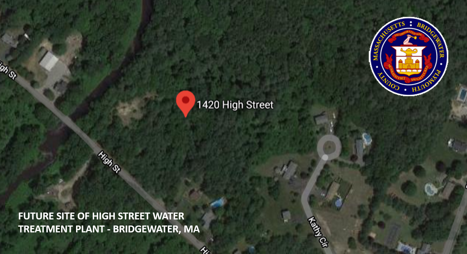
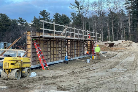
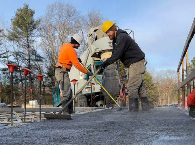
The High Street Water Treatment Plant project is located at various sites throughout the Town of Bridgewater, Massachusetts including:
- High Street Water Treatment Plant located at 1420 High Street / High Street Well Field located at 1425 High Street / Maintenance Garage located at 1400 High Street / Carvers Pond Water Treatment Plant located at 100 Wellfield Drive / Plymouth Street Wells (Well 10A and 10B) located at 1729 Plymouth Street / Sprague Hill Water Storage Tank located at 0 Broad Street (entrance across from 596 Broad Street) / Great Hill Water Storage Tank located at 240 Rear Burrill Avenue
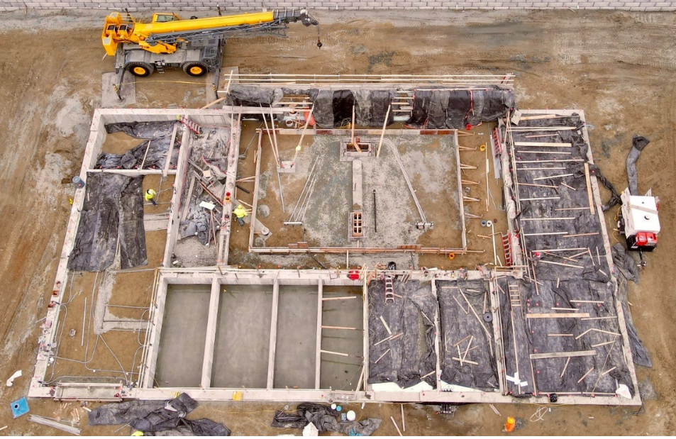
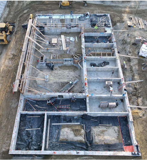
Construction of the High Street Water Treatment Plant. The major proposed work under this contract includes but is not limited to:
1. Work at the High Street Water Treatment Plant site is described as follows:
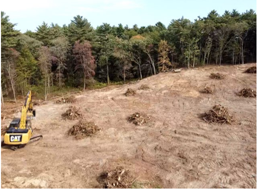
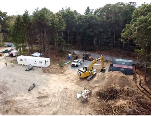
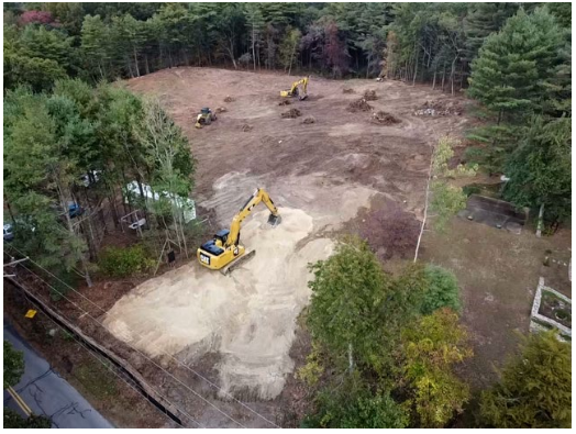
- Civil site work including site development, land clearing, earthwork, backwash lined lagoons and infiltration basin, drainage, site process piping, site utilities, site lighting, pavement, gravel drives, chain-link fence and gates, retaining walls, septic system tank, leaching field and pump station;
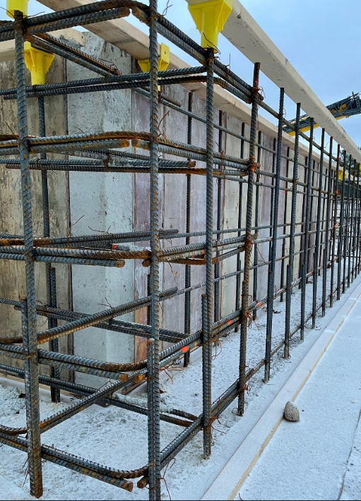
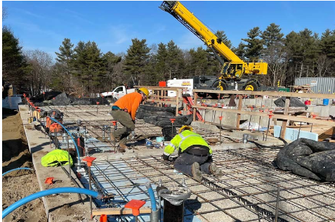
- Water Treatment Plant building including concrete foundation and pads, masonry block, roofing systems and flashing, windows and doors, walls, miscellaneous metalwork, break room, control room, laboratory, bathroom/locker rooms, chemical room, filter room, pump room, mechanical room, electrical room and various structural and architectural associated items as indicated on the drawings;
- Process equipment including two (2) greensand plus water filtration units with aeration towers and associated blowers, two (2) finish water distribution pumps and process piping, Potassium Permanganate, Sodium Hydroxide and Sodium Hypochlorite chemical equipment including feed pumps, piping, day tanks, bulk storage tanks, and a UV reactor;
- HVAC, plumbing and fire protection systems as indicated on the drawings;
- Electrical systems including a new electrical and telephone services, pad mounted emergency generator and transformer, Automatic Transfer Switch (ATS), Motor Control Center (MCC), Variable Frequency Drives (VFDs), lighting, site conduits and electrical manholes and other associated items as indicated on the drawings;
- Instrumentation and Control systems including construction of new Supervisory Control and Data Acquisition System (SCADA) and system wide Radio Telemetry communicated network. Installation of new instrumentation equipment including PLC operated control panels with OIT interface and installation of various instruments as indicated on the drawings.
2. Work at the High Street Well Field is described as follows:
- Site demolition including pavement, piping, liquid propane storage tanks and concrete pads;
- Rehabilitation of existing site including pavement, grading and drainage improvements, site piping and utilities;
- Temporary electrical service installed for Well Pump Station No. 6;
- Rehabilitation of Well Pump Station No. 8 including demolition of existing chemical feed and storage equipment, concrete containment wall and pads, MCC, emergency generator and various electrical equipment. Rehabilitation of well pump and piping, painting, HVAC and electrical equipment;
- Replacement of submersible Well Pump No. 9;
- Site electrical work including upgrades to electrical service to Well Pumping Station No. 8 and removal of service for Well Pump Station No. 3, new pad mounted emergency generator and associated power and fiber communication conduits and wiring and manholes
- Rehabilitation of Well Pump Station No. 3 including replacement of well pump and piping, installation of HVAC equipment, electrical equipment, and painting;
- Rehabilitation of Well Pump Station No. 6 including replacement of well pump and piping, installation of HVAC equipment, electrical equipment, roof and hatch replacement, brick repointing repairs and painting;
- SCADA system upgrades at each of the well pumping stations including new control panels, new instrumentation and connection to new fiber network.
3. Work at the Maintenance Garage is described as follows:
- All work conducted at the Maintenance Garage (all work at 1400 High Street) to be included in Bid Alternate 1 as defined by Section 01 10 00 Measurement and Payment;
- Site demolition including existing concrete tanks, strictures and pads, pavement, piping, bollards and gas storage tank;
- Rehabilitation of existing site including pavement, grading and drainage improvements, site piping and utilities including new water and natural gas services;
- Installation of new septic system tank and leaching field;
- Demolition of existing pre-engineered metal garage building including all existing building components down to the foundation. Existing foundation to be utilized for construction of new pre-engineered metal garage building;
- Construction of new pre-engineered metal garage building with an addition including architectural, structural, HVAC, plumbing and electrical systems. Building addition to include a break room, locker room, bathroom and mechanical room.
4. Work at the Carvers Pond Water Treatment Plant is described as follows:
- SCADA system upgrades including new internal ethernet network within the treatment facility with connection to a fiber network for the remote wells;
- SCADA system upgrades including the removal and replacement of components within the existing Process Control Panel, Chemical Feed Control Panel and Filter Control Panel including but not limited to PLC, OIT, power suppliers, ethernet switch and UPS;
- SCADA system upgrades including the installation of new Supervisory Control and Data Acquisition System (SCADA) inclusive of workstations, printer, reporting and alarm software and radio telemetry system including new antenna;
- SCADA system upgrades at each of the 3 remote well sites including new control panels, reconnection of existing instrumentation and connection to new fiber network.
5. Work at the Plymouth Street Wells (Well 10A and 10B) is described as follows:
- SCADA system upgrades including the removal and replacement of components within the existing control panel including but not limited to PLC, OIT, power suppliers, ethernet switch, UPS and radio system including new antenna.
6. Work at the Sprague Hill Water Storage Tank is described as follows:
- SCADA system upgrades including new control panel, reconnection of existing instrumentation, new radio system including tank mounted antenna.
7. Work at the Great Hill Water Storage Tank is described as follows:
- SCADA system upgrades including new control panel, reconnection of existing instrumentation, new radio system including tank mounted antenna.

